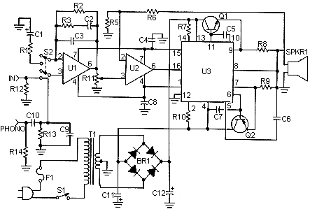
50 Watt Amplifier Circuit
This is a handy, easy to build general purpose 50 watt amp. The amp has an input for a radio, TV, stereo or other line level device. It also has a phono input for a record player, guitar, microphone or other un-amplified source. With the addition of a low pass filter at the input, it makes a great amp for a small subwoofer.
parts
R1 200 Ohm 1/4 W Resistor
R2 200K 1/4 W Resistor
R3 30K 1/4 W Resistor
R5 1K 1/4 W Resistor
R6 5K 1/4 W Resistor
R7,R10 1 Meg (5%) 1/2 W Resistor
R8,R9 0.4 Ohm 5 W Resistor
R11 10K Pot
R12,R13 51K 1/4 W Resistor
R14 47K 1/4 W Resistor
C1 100uF 35V Electrolytic Capacitor
C2 0.011uF Capacitor
C3 3750pF Capacitor
C4,C6 1000pF Capacitor
C5,C7,C8 0.001uF Capacitor
C9 50pF Capacitor
C10 0.3uF Capacitor
C11,C12 10,000uF 50V Electrolytic Capacitor
U1,U2 741 Op Amp
U3 ICL8063 Audio Amp Transister Driver thingy
Q1 2N3055 NPN Power Transistor
Q2 2N3791 PNP Power Transistor
notes
1. I know I skipped R4. That is not a problem :-)
2. Distortion is less than 0.1% up to 100HZ and increases to about 1% at 20kHz.
3. I haven't been able to find anyone who sells a suitable T1. You can always use two 24V 5A units in series. If you are building two amps (for stereo), then I would suggest using an old microwave transformer and rewinding it.
4. Q1 and Q2 will require heatsinks.
5. You may have trouble finding U3 because it is discontinued. Please don't email me about sources...I can't find it either. A possible source was sent in by JBWilliams ( [email protected] ):
Zigma Electronics
8803 Shirless Ave.
Northbridge, CA 91324
United States
Phone: 818-772-7590
author:unknown, none

