Emergency Light & Alarm Circuit
Powered by two AA NI-CD batteries
Four switchable options
Circuit diagram
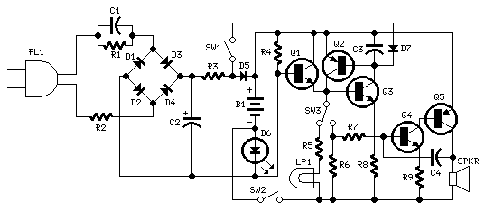
Parts:
R1 220K 1/4W Resistor
R2 470R 1/2W Resistor
R3 390R 1/4W Resistor
R4 1K5 1/4W Resistor
R5 1R 1/4W Resistor
R6 10K 1/4W Resistor
R7 330K 1/4W Resistor
R8 470R 1/4W Resistor
R9 100R 1/4W Resistor
C1 330nF 400V Polyester Capacitor
C2 10�F 63V Electrolytic Capacitor
C3 100nF 63V Polyester Capacitor
C4 10nF 63V Polyester Capacitor
D1-D5 1N4007 1000V 1A Diodes
D6 LED Green (any shape)
D7 1N4148 75V 150mA Diode
Q1,Q3,Q4 BC547 45V 100mA NPN Transistors
Q2,Q5 BC327 45V 800mA PNP Transistors
SW1,SW2 SPST Switches
SW3 SPDT Switch
LP1 2.2V or 2.5V 250-300mA Torch Lamp
SPKR 8 Ohm Loudspeaker
B1 2.5V Battery (two AA NI-CD rechargeable cells wired in series)
PL1 Male Mains plug
Device purpose:
This circuit is permanently plugged into a mains socket and NI-CD batteries are trickle-charged. When a power outage occurs, the lamp automatically illuminates. Instead of illuminating a lamp, an alarm sounder can be chosen.
When power supply is restored, the lamp or the alarm is switched-off. A switch provides a "latch-up" function, in order to extend lamp or alarm operation even when power is restored.
Circuit operation:
Mains voltage is reduced to about 12V DC at C2's terminals, by means of the reactance of C1 and the diode bridge (D1-D4). Thus avoids the use of a mains transformer.
Trickle-charging current for the battery B1 is provided by the series resistor R3, D5 and the green LED D6 that also monitors the presence of mains supply and correct battery charging.
Q2 & Q3 form a self-latching pair that start operating when a power outage occurs. In this case, Q1 biasing becomes positive, so this transistor turns on the self latching pair.
If SW3 is set as shown in the circuit diagram, the lamp illuminates via SW2, which is normally closed; if set the other way, a square wave audio frequency generator formed by Q4, Q5 and related components is activated, driving the loudspeaker.
If SW1 is left open, when mains supply is restored the lamp or the alarm continue to operate. They can be disabled by opening the main on-off switch SW2.
If SW1 is closed, restoration of the mains supply terminates lamp or alarm operation, by applying a positive bias to the Base of Q2.
Notes:
Close SW2 after the circuit is plugged.
This circuit was awarded with publication in ELECTRONICS WORLD "Circuit Ideas", September 2001 issue, page 708.
author:RED Free Circuit Designs,
website: http://www.redcircuits.com/