PC Output Interface
Disclaimer:
Every reasonable care has been taken in producing this information. However, the author can accept no responsibility for any damage arising from mis-use of this information. Please also see this sites general Disclaimer.
Description:
A versaile output interface that can control external devices direct from your computer. Uses freely available software and works with both windows and Linux.
Notes:
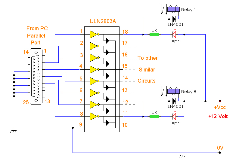
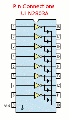
Any PC that has a free parallel printer port available should work with this circuit. The schematic shown above requires little explanation. Any data sent to the printer port is already "latched" and just requires buffering to be able to drive an external ciruit. In this case I have chosen to use the ULN2083 octal transistor array to buffer the output current from the parallel port. The IC pinout for the ULN2083 is shown below.
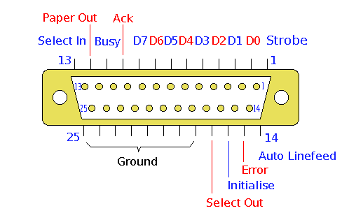
The pararell printer port on your PC is a 25 way D type connector. Its pinout is shown below. Pins 2 to 10 are the data output lines D0 to D7. Pins 18 through 25 are ground pins, the other pins are not used and left unconnected.
The output current is amplified by the ULN2083 and each output pin can supply a load of up to 50mA. The outputs are active low, meaning that a high logic input gives a low logic output. To get around this the output load is routed to a positive voltage, so that any high input will now produce a high output. The positive supply can be any value from +5 to 50Vdc, I used 12V relays and so used a 12V supply in my design.
Software Control:
All that is needed is a way to send data to the printer port and control the output circuits. The program I have chosen to work with this interface is Parashell, created by Brett Carol and hosted on Sourceforge. The software is free to use and as of Version 2.1 will work both on Windows and Linux. A quick install guide follows for both operating systems.
Installation on Windows:
Unzip the file parahell-2.1.zip With Windows Xp simply clicking on the file will expand its contents. Double click on the bin, hen the windows folder, and drag the file parashell to your desktop. Open a command prompt and proceed as in Testing.
Installation on Linux:
RPM Based e.g. Suse, Fedora, Mandriva:
In this example I am using Suse 10.1 First download Parashell to your home directory, click here for the link. At the time of writing the current version is parashell-2.1.zip
Download parashell-2.1.zip to your home directory, then open a terminal and unzip the package (as the package contains binaries for both windows and linux it is compressed in zip format instead of the usual .tar.gz and .tar.bz2 linux formats.)
Code:
unzip parashell-2.1.zip (If unzip is not on your system use yast or yum to install it)
cd parashell/bin/Linux (change into the linux binaries folder)
chmod 4755 parashell pin (change mode to setsuid permissions)
su (enter root password)
mv parashell pin /usr/bin (copy files for system wide use)
exit
cd (change to home directory again)
Debian based e.g. Ubuntu, Knoppix, Debian Etch:
I can find no readily available debian package so just follow the instructions above for rpm based distributions.
Testing:
Connect the PC output interface to the printer port on your computer. If your computer only has one parallel port then its address will be 378 (in hex). This is represented by 0x in the parashells syntax. Once the software is installed open a command prompt (windows) or terminal (linux) and type:
parashell 0x378 255
This will sete all eight data lines to high, D0 to D7, and activate all LEDS and relays.
Then type:
parashell 0x378 0
This will set all eight data lines to low and turn off all LEDS, relays and external circuits.
Controlling Individual Pins:
Parashell output commands are in decimal, the outputs D0 through to D7 are in binary. Hence if you want to control individual pins you just look up their value in the binary to decimal conversion table below. For example, if you had a circuit connected to pin D5 then you would use parashell 0x378 32 to enable D5, and 0 to disable it. If you had circuits connected to D2 and D3 and wanted to make them active at the same time, then add the decimal values together, i.e. parashell 0x378 12 would simultaneously activate D2 and D3.
Binary to Decimal Conversion Table
D7 128
D6 64
D5 32
D4 16
D3 8
D2 4
D1 2
D0 1
Data Pin Output Value
All outputs remain latched until a zero is sent to the desired output pin. If you had multiple circuits, then sending the command parashell 0x378 0 would turn all outputs off. This may be undesirable and if for example you had circuits connected to D0, D1, D2 and D3 and you had outputs D0,D2 and D3 set to on, and D1 was off and only wanted to switch off D2, then look again at the table above. D3 would be on,(value 8), D2 would be off (value 0), D1, would be off (value 0) and D0 would be on (value 1) Sending 9 or parashell 0x378 9 would have the desired effect.
Pin Command (Linux Only)
The pin command is a quick way to check which outputs are set and which are not set. Open a terminal and type:
pin 0x378
This will return the decimal value of the output status, e.g. if pin returned 255 then all outputs would be on.